questions concerning ackerman, flipping spindles, etc
574 views
7 replies
4 following

questions concerning ackerman, flipping spindles, etc

e10pvmt
+1y
Max you have been a giant help and i hope you could help me solve a few concerns i have.....i have finally pulled my frame off the rak and set it on the ground....while at slamfest i discussed a few things with some friends of mine that i need to address.....i was reading over the Ackerman thread last night and i think i am beginning to understand the logic.....the concern i have is i am using a rack and pinion steering with a spindle that was originally used with a drag link suspension from a toyota pickup.....if i understand correctly you should be able to draw an imaginary line ffrom the center of the rear end through the lower ball joint and through the steering tie rod joint.....well the way mine is that imaginary line dosent.....it would taper away from the rear end.....would there be any issues in flipping the spindles and rack and making it a rear steer....i believe previously you said brakes in front or behind the axle line dosent really matter (correct me if i am wrong). When i was discussing it with my friend he mentioned just moving the tie rod point on the spindle out towards the rim but i am concerned with cutting the spindle as well as losing clearance for brakes and wheels. there are some new pics of the setup in my profile but i have a top pic but dont have access to it right now....i will have to post it up later this week when i get home....hope you can be of some assistance....and thanks in advance

BioMax
+1y
Once you understand how to set up Ackermann, you will be able to simply look at a vehicle and tell if it will work or not. The problem is understanding what is happening in the first place.
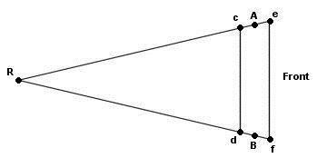
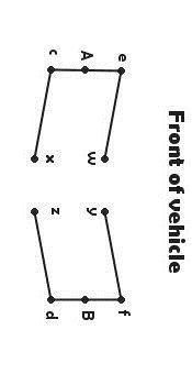
The top diagram is the traditional Ackermann diagram used to calculate steering arm angles. The bottom diagram is a modified version of the first one that takes in to consideration that an a-arm suspension has seperate tie rods that can be moved around to change the steering arm/tierod relationship.
The way to use these two diagrams is to figure out the angle needed by using the top diagram and then applying the angle to the lower diagram to figure out where to mount the center link or steering rack.
For example, on a front steer vehicle you would need to find angle "Ref" based on the length and width of your vehicle ("R" being the center of the rearend, "e" being the left outer tierod and "f" being the right outer tie rod) then take that angle and apply it to the bottom diagram "Aew" ("A" being the lower ball joint, "e" being the outter left tierod and "w" being the left inner tierod. The difference between the two diagrams is that the placement of line "Ae" is determined by the spindle that you are using and "w" is how far foward or back the inner tierod would need to be mounted in order to equal the original angle of "Ref" from the top diagram.
I'm not sure how else to describe that, so I hope it helps.


BioMax
+1y
I always forget to explain the other lines...
These diagrams have been drawn to figure out both front and rear steer ackermann. "A" and "B" are lower ball joints, "e" and "f" are front steer steering arms and "c" and "d" are rear steer steering arms.
These diagrams have been drawn to figure out both front and rear steer ackermann. "A" and "B" are lower ball joints, "e" and "f" are front steer steering arms and "c" and "d" are rear steer steering arms.

e10pvmt
+1y
i think i get it....so i would move te rack back so that the angle AEW matches the angle REF.....now i know its difficult to comment without seeing it but i shouldnt have any isses then with using the rack vs running a drag link....right? i definitley have to move it back...the way i did it i made the tie rod parallel o the crossmember so everything attaching to the spindle is at right angles.....Max, thanks again.....its really not that difficult a concept once you make it easy to understand...thank god for my years and gallons of legos...lol

flatblack92
+1y
Max, you said that "e" on the first diagram was the front steer tie rod pivot. That would be the hypothetical perfect placement for perfect ackerman, correct? The first diagram would be used to find the angle, which would be used with the actual tie rod pivot to find the inner steering pivot. Setting up ackerman is just moving the inner steering pivot forwards or backwards without changing the width or the height from the positions that give minimal bump steer. Also for a rear steer setup would you use angle "Acd" from the first diagram. Thanks, Alex

BioMax
+1y
Tony, I do believe you got a good handle on it. Though you mentioned that your tierods are parallel to the crossmember right now and that you need to move the rack, that isn't necessarily true. Your tierode could be parallel to the crossmember if the outter tierods "e" and "f" were wider than the lower ball joints "A" and "B". Your rack placement, front to back, is going to be determined by the steering arm angle.
flatblackmazdawg- The top drawing would be used to calculate "perfect" Ackermann steering. The thing is that Ackermann isn't necessary. S-10s actually have a small amount of anti-Ackermann, some vehicles like too much and some don't want any. Obviously I answerd your question about inner tierod placement in my response to Tony and you are correct in your assumption about "Acd" being for rear steer.
flatblackmazdawg- The top drawing would be used to calculate "perfect" Ackermann steering. The thing is that Ackermann isn't necessary. S-10s actually have a small amount of anti-Ackermann, some vehicles like too much and some don't want any. Obviously I answerd your question about inner tierod placement in my response to Tony and you are correct in your assumption about "Acd" being for rear steer.

e10pvmt
+1y
i think i got it now...but its a toyota drop spindle and i believe the tie rod hole is almost on the same plane as the lower ball joint....it isnt wider if anything its a lil narrower...but without looking at it i couldnt tell you...but i figure as long as i can get that angle close i should be good....but i really appreciate the help....your a stress saver

BioMax
+1y
Haha. I'm glad I can help out.
Related Discussions in Ask A Pro
Thread
Posts
Last Post
0
T
last post by
twistedmetal2188 +1y
4
H
last post by
himynameischance +1y

