tie rod angles

msturg
+1y
I've looked through the books I have currently about designing the front suspension, but I don't really see anything particular about what angle the tie rods should be from a front view. I know where to place the inner pivot to ensure no bumpsteer, as far as along the imaginary line between the upper and lower control arm pivot points. My problem is I don't really have an upper control arm limiting my location of the line, what I really want to do is define the lower control arm inner pivot so that when at ride height the angle of the lower control arm is near level with the ground or at a slight upward angle.
From there I would like to mount the rack and pinion fairly close to this pivot so that my upper arm is about 80% the length of my lower. However I want to make sure that I'm not setting the angle of the tie rod too steep, but I haven't really found anything telling me that it should be at the same angle as the lower or any sort of definition from a front on view.
I know there is a lot of babble in there so I can throw a pic up if need be to explain what I'm asking

msturg
+1y
Just realized that I probably should have posted this in suspension forum not ask max

BioMax
+1y
Edited: 1/18/2009 1:42:11 AM by BioMax
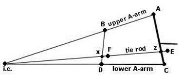
This is the basic diagram that you would use to determine the proper placement of your steering pivots. I'm not sure what you are saying about not having upper A-arms to "limit the location of your line" though.<a href="http://s94.photobucket.com/albums/l103/56buick/?action=view&current=a-armpic.jpg" target="_blank"><img src="http://i94.photobucket.com/albums/l103/56buick/a-armpic.jpg" border="0" alt="front suspension"></a>
This is the basic diagram that you would use to determine the proper placement of your steering pivots. I'm not sure what you are saying about not having upper A-arms to "limit the location of your line" though.<a href="http://s94.photobucket.com/albums/l103/56buick/?action=view&current=a-armpic.jpg" target="_blank"><img src="http://i94.photobucket.com/albums/l103/56buick/a-armpic.jpg" border="0" alt="front suspension"></a>

TwistedMinis
+1y


BioMax
+1y
Thanks Seth. I didn't realize that there is a new picture protocol. Haha!

TwistedMinis
+1y
I've always been curious about that picture. I'm assuming the tie rod pivots are points "F" and "E". Why are the pivots not "x" and "z" which are in line with the balljoint and bushing pivots? Or is this maybe just illustrating different acceptable mounting points, or even just the range of motion they will travel through?

BioMax
+1y
x and z would be the calculated tierod lengths, but that would only work if Ackermann didn't exist or you had a spindle with no Ackermann built in. F and E would be the actuall placement of the tierod points assuming you had a front steer system with Ackermann. Rarely will you find a spindle where the tierod is in line with the upper and lower balljoints. Does that make more sense?

TwistedMinis
+1y
Ya I understand that now. I never really understood the extra points on the diagram though.
Related Discussions in Ask A Pro
Thread
Posts
Last Post
0
T
last post by
twistedmetal2188 +1y
4
H
last post by
himynameischance +1y

