Michigan Metal Works ---- Updates : Please Read.
83577 views
1319 replies
232 following
Michigan Metal Works ---- Updates : Please Read.

jeebus @ mmw
+1y
Thanks!
Taylor
Taylor

BIGJEFF64
+1y
the work looks epic bro i will be doin some ordering come tax time

jeebus @ mmw
+1y
Just updates. Nothing special. Nothing un-ordanary. Building shit all day, still lol
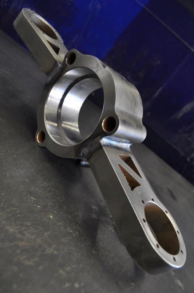
Some new spindles getting built, as well as a fully fabricated front suspension from scratch. I will elaborate more on that soon, but just some teasers to get you by currently.
These are the arms for the previous spindles built, as you can see, they turned out pretty slick!
Camp - N - Drag 2012
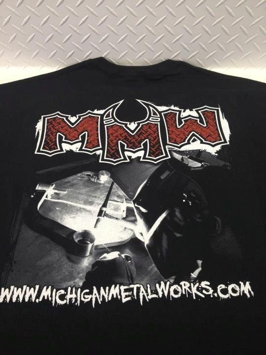
New shirts available as well!

Rob Clayhill
+1y
You should give yourself a pat on the back for me, this stuff looks great. Sorry for my lack of knowledge but what is the "balljoint" setup called on the latest spindles you made? This is the first time ive seenasnything like it.
Also i sent you an email about a shirt, if you got it ill buy one.
Also i sent you an email about a shirt, if you got it ill buy one.

e10pvmt
+1y
looking bad ass as always......I would love to see someone put together a full hub to hub IFS to fit our minitruck/fullsize truck chassis needs.

jeebus @ mmw
+1y
Okay, so lately i have been deep into this suspension build for a Trailblazer SS project going on at California Fab Shop. They were building a true AWD trailblazer with a very heftily built motor, and wanted to lay it out flat on 22" billets.
I have worked with Kris Carroll in the past on a few of his projects, so when he asked me help with this one, i said yes right away, but was not prepared at all for how many hours of time i would have into it. I have no pictures of this begining process, so bare with me, you will have to go from description alone while i describe the job.
One day in may, a pallet showed up at the shop, it pretty much had the entire hub to hub front suspension from a trailblazer ss on it. At the time i was really busy with other work, so i unpacked it all, glanced it over and saw what a mess the stock suspension was on that thing, but didnt really have time to look too deeply into everything.
When the time came to work on this thing, i decided that literally every thing on this trucks stock suspension, had to be tossed in the poop can. It was useless. The only thing kept from the stock suspension was the wheel hubs, everything else got scrapped.
The goal on the truck was to lay it out on 22" billet wheels, while getting 10+ inches of suspension travel, and retaining the AWD. I started by cutting up pieces of cardboard to simulate the arms, spindles, and rotors and just started figuring mounting points for all of these parts, while being able to keep a really usable camber arc. Obviously, to little camber and the wheels wont tuck into these hellish shaped fenders that i was told i had to work inside, and too much camber and it would be useless. Keep in mind, i had to figure this stuff out, with no vehicle to refrence or sheetmetal to measure, just good ole email communication haha. Then, while keeping their fabricated frame in mind i had to refrence the mounting points onto their frame, so they could get some mounting points started.
After a few hundred hours of figuring mounting points, camber and caster details and how the mounts would improve or hurt one or the other, i was able to settle on a space the parts needed to be built in. Now it was time to design the actual parts. Kris said they were going with an industrial type theme, and were using a lot of hex head bolts, and what not all over the place, so going with their theme, i came up with a design.
Then it was time to make it happen.
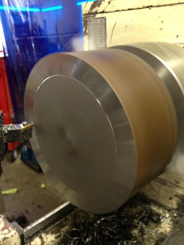
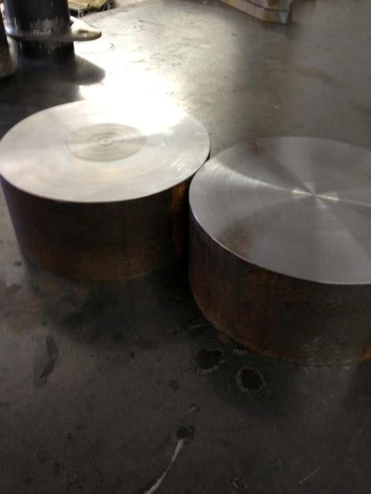
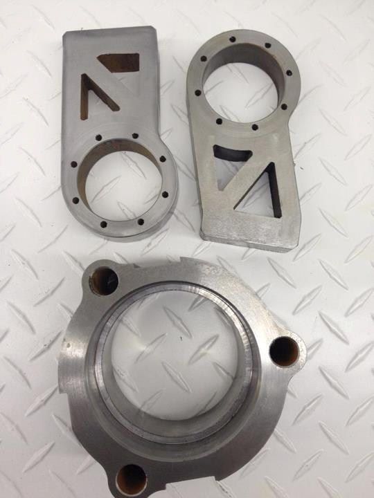
Started on the hubs that the spindle would be built around. Settled on 8" diamiater 3" thick slugs.
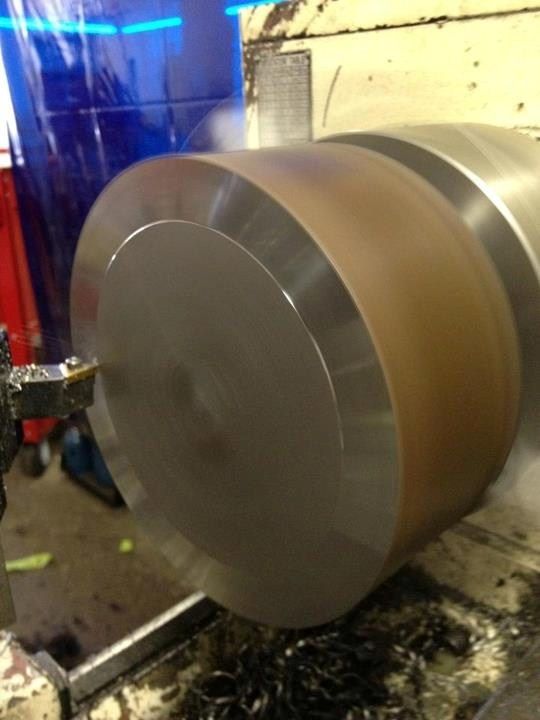
Faced them to a true 3" thick:
Then, i would water jet the shape out of the slug, that i wanted for the hub base, first time i tried it i programmed something wrong, and ended up with a very expensive pair of paper weights:
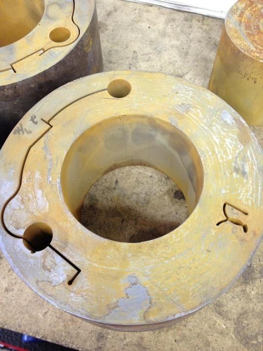
So, the process started again, slugs, faced, water jetted. I then machined the bore i wanted into the slugs, so the hub would sit flat into them and have a pocket of material:
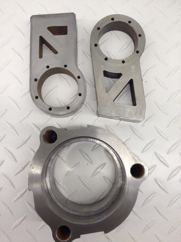
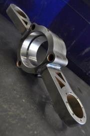
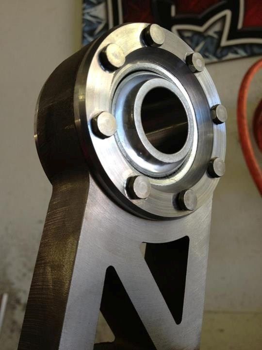
Then, waterjet cut the pivot points for the spindles out of 1.5" solid material, and machined it true flat. On this design, I decided to mount the uniballs sideways so they would get unlimited travel, without binding, with how short the arms were, it was our best bet, so i came up with a design that required no welding of a cup, but was machined to fit correctly in the slugs, and assemble together with hex head bolts, making a very clean and simple install, that kept an industrial theme, also machine the retaining rings for the bearing that sits in the main housing. again, these were designed for maximum travel, but also i wanted them to look really good:
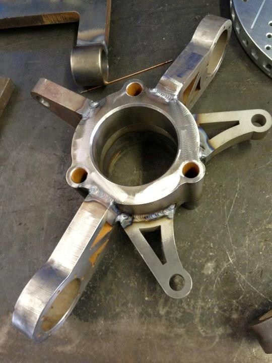
Then, really it was time for a lot of welding. and when i say a lot of welding, thats what i mean. In the material prep work, and welding time, there is over 100 hours into it. In my shop, everything has to be sand blasted, and polished before tig work, so everyghing had to get blasted and polished, then all was TIG welded in place. When i design the parts i make them sort of jig together, so they fall into place, and dont require any elaborate jigs to assemble, but, on this particular one, since the material was so thick, i made a place jig so when i welded the main structure, it did not warp at all. Welding photos:
As you can see from those pics, a steering arm was designed and added, as well as a caliper mount that will hold the pair of Baer 6p calipers that are to be installed.
Anyways, after it was all welded up, i wanted to test assemble the spindle to see what it looked like, and i was super stoked, it looked and functioned great.
Now, obviosly you can see in those last few pics, we designed, and built arms as well. They were a bit simpler in the process, but unique none the less. Since i went with the horizontal uni-ball design, the arms had to accomidate it. Its all .750 plate, and .500 plate. The uppers are shaped in a way so that it clears the tire at all times of the turn also.
I hope to be able to take more pictures of it tommorrow fully assembled with the calipers and rotors, but time might not allow it.
Hope you liked the quick write up on it, Im not a big dog shop so i didnt have any film crew here to document it or anything, i would really have liked to capture the whole process with all the machining and all, but keep in mind during this entire build of these, i had to fill about 450 other orders as well, and counting! hahaha.
Taylor

DisseveredCustoms
+1y
Taylor your the man dawg!!!!!!!!!!!!!!!!!!!


jeebus @ mmw
+1y
Thanks!

BIGJEFF64
+1y
those welds are super clean!!!!! awesome job as usual bro
X
xgolferdude
+1y
Super nice man!
Related Discussions in Mini Truckin General
Thread
Posts
Last Post