What is steering Ackermann?

e10pvmt
+1y
i havent built it yet but i guess you can call it preliminary...i went off the idea behind a mustang II but using a taller spindle off of a 88-94 toyota pickup.

BioMax
+1y
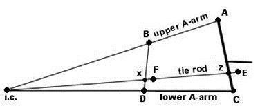
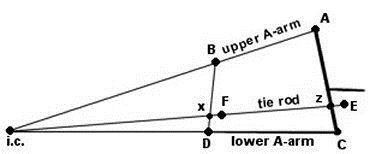
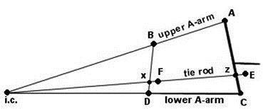
Okay, as far as your grasping the tierod placement you're good, but parallel a-arms isn't. You need to make a "paper doll" of your design and see what happens as the suspension cycles. Your final design will look more like the pic below. The inner points should be closer together to help keep camber to a minimum. I know that it doesn't look like it would, but it does. Before you build anything reading both "Tune to Win" and "Engineer to Win" (both by Carroll Smith) would be a GOOD idea.

G
granth
+1y
Edited: 8/18/2007 7:05:50 PM by 72bumpside
Originally posted by BioMax
Okay, as far as your grasping the tierod placement you're good, but parallel a-arms isn't. You need to make a "paper doll" of your design and see what happens as the suspension cycles. Your final design will look more like the pic below. The inner points should be closer together to help keep camber to a minimum. I know that it doesn't look like it would, but it does. Before you build anything reading both "Tune to Win" and "Engineer to Win" (both by Carroll Smith) would be a GOOD idea.
Max, I actually have "Tune to Win" right in front of me, reading the ackerman section that he wrote. This book goes a good ways into detail about things that affect ackerman and all.
For example, slip angle, is this something we need to think of?

G
granth
+1y
"If you take that angle and plug it into your spindle/balljoint relationship you will end up with something like what is shown in diagram 2. The center tierod points are moved back because the steering arm on the spindle is closer to the center of the vehicle. the angles Aew and Bfy are equal to Aef and Bfe. If it were a rear steer it would be the same for the involved angles. If the steering arm on the spindle was further out from the center (on a front steer) then the original diagram, then the center tierod points would be further foward in order to keep with our figured angle from the original ackerman diagram."
I understand your first post up until this point, probably because I have no "parts" in front of me. The way to get your angle s from your lower ball joint, to your tie rod, to the center line of the vehicle, or rear end, whatever. Just for the sake of asking, this is given your rear end has the pumpkin centered correct? its more or less the center of the vehicle that you are measuring to?
You say to "plug in your angle to the balljoint/spindle relation, but what exactly does that mean? What are you doing with the 80 degrees, as you used in your example? Also, when you go to set your inner tie rod placement, will it not be the same on both sides? I am guessing when you figure out the whole balljoint/spindle deal with your newly found angle, this sets where your inner tie rod mounts should be, correct? So I guess my main question is what exactly are you doing with that number?
Does this hold true with rack and pinion as well?

e10pvmt
+1y
Originally posted by BioMax
Okay, as far as your grasping the tierod placement you're good, but parallel a-arms isn't. You need to make a "paper doll" of your design and see what happens as the suspension cycles. Your final design will look more like the pic below. The inner points should be closer together to help keep camber to a minimum. I know that it doesn't look like it would, but it does. Before you build anything reading both "Tune to Win" and "Engineer to Win" (both by Carroll Smith) would be a GOOD idea.
here is a link to the diagrams i was using to get my idea
http://www.heidts.com/heisinfo.htm


BioMax
+1y
72bumpside- The basic drawing that everyone refers to when describing ackermann only applies directly to staright axle vehicles where the tierod would attach to both left and right knuckles (spindles.) What I have tried to explain here is that you have to address a-arm suspensions differently. You would still use the basic triangle diagram to figure out your tierod angles, but you would have to move your inner tierods either foward or backward in order to make them work with your particular design. Most beginers assume that ackermann is only in the knuckle, but in reality it is the relationship between the knuckle and the inner and outter tierod points.
What I mean by "plug in your angle to the balljoint/spindle relation" is that you need to take your particular vehicle's measurements figure them into the basic triangle diagram, and find out what your tierod/steering-arm angle should be. From there you can use the second diagram to figure out where your inner tierod points should be based on your actual knuckle geometry.
As for considering tire slip angles into your calculations... I don't think that you need to worry about that. If you read Engineer to Win, you will see that even Carroll has not yet figured out what is the "right" amount of ackermann. The diagram only addresses angles that would allow the tires to follow each inner and outer turning radius without any theoretical tire scrub.
And when using the basic Triangle diagram, you do not use the pumpkin for your "center" you use exactly center of the rearend housing, whatever it may be. Front wheel drive vehicles need ackermann too, but they don't have rearends with "pumpkins."
Tony- I see what you are thinking, but the Mustang II stuff has a realitively short upper arm and it could benefit from some minor tweaking. I would still STRONGLY suggest making a paperdoll of your design and make some simple changes to the pivot points and see what happens.
B
BDon20s
+1y
Can we discuss the purpose of GM's odd lower control arm angles, not on a horizontal plane but in a front to back relation? What is the purpose of this?
G
granth
+1y
Originally posted by BioMax
72bumpside- The basic drawing that everyone refers to when describing ackermann only applies directly to staright axle vehicles where the tierod would attach to both left and right knuckles (spindles.) What I have tried to explain here is that you have to address a-arm suspensions differently. You would still use the basic triangle diagram to figure out your tierod angles, but you would have to move your inner tierods either foward or backward in order to make them work with your particular design. Most beginers assume that ackermann is only in the knuckle, but in reality it is the relationship between the knuckle and the inner and outter tierod points.
What I mean by "plug in your angle to the balljoint/spindle relation" is that you need to take your particular vehicle's measurements figure them into the basic triangle diagram, and find out what your tierod/steering-arm angle should be. From there you can use the second diagram to figure out where your inner tierod points should be based on your actual knuckle geometry.
so, you draw a line from ball joint, to your steering joint on your spindle, to the center line of the rearend. and then find the angle (for rear steer) at RCD? Am I seeing that right? I guess my problem is I don't understand the whole using the angle from the first diagram, in the second diagram. Hell, I may be looking at it completely wrong.

BioMax
+1y
72bumpside- You are assuming that the diagram has the steering points already in it. The simple triangle is a straight line drawn through the front lower balljoints, and a line drawn through each lower balljoint to the center of the rearend. The angle that is created at each of the lower balljoints by the intersection of each line is your "perfect" tierod/steering angle for creating ackermann. The problem comes when your knuckle does not have the same balljoint/steering angle that is represented in the triangle diagram, then you need to refer to the second diagram and plot your knuckle dimentions into it in order to figure out proper inner tierod placement.

BioMax
+1y
Nick- I have often times wondered the same thing. I do have my own oppinions about what the designers might have been thinkin' but they are just assumptions. What you do need to remember when looking at factory designed suspension though, is that they were designed for even the worst drivers to be able to make mistakes without major consequences. Auto manufactures design their front suspensions to loose traction before the rear suspension just to keep things under control. If the front suspension (while cormering) begins to slip, your first reaction would be to let off the gas, that will imediately transfer weight onto the front end regaining traction. But if the rearend were to loose traction in a corner, the vehicle gets a whole lot tougher to control. SO most of my speculations are that GM wants their suspension to work really well when NOT being pushed, but to give up when it IS being pushed.
Related Discussions in Air Ride Suspensions
Thread
Posts
Last Post

