1990 B2200 Ground Up
R
robert_paulsen
+1y
that would be cool how much to do the cad file? it would be to spec?
S
slowroller
+1y
First let me say your old builds were radical and awesome. So sorry to hear the second one was crushed.
On to the front end geometry topic.
Now my truck is setup totally different. I modified stock geometry to work with a 2" static ride height, so I have considerably less range of motion.
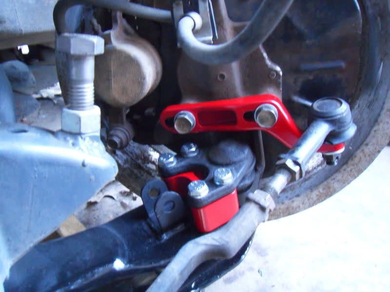
I moved my upper control arms up around 1" and Made them adjustable for caster. I also re designed the steering arm to spindle mount to tune out bump steer, (which is super easy on these trucks since the steer arm bolts to the spindle).
I design a lot of race geometry suspension. If I were building a frame I wouldn't consider anything but rack and pinion steering. More important than overall width (which can easily be changed) is inner to inner pivot width. That width must suit the rest of your geometry or you will never be able to tune out bump steer or toe change.
Keep up the good work.
S
slowroller
+1y
Also I have an 86 Carrolla and I'll be willing to measure the rack.

vsawmike
+1y
This is why I am staying close to factory geometry in the arms from one to the other. I know the biggest rule in this is the drag link width needs to match the line from the upper arm bushing to the lower so toe change is minimal. I plan to make some test pieces from wood and cycle it all to see what happens.
The only thing I dont know about for sure is where to mount the tie rods. Above like factory or below the spindle. I may have to end up changing it a few times to get it right.
My last one I used factory geometry and a Tacoma rack flipped over to use for right hand drive. The toe change was bad. So this time I cant use that and as narrow as this thing will be I may have to use a unisteer rack or a modified pinto rack. Something very narrow.
I do have three books on suspension design and I ahve done several before. But I have not changed any this much.
So what is the best rule in keeping bump steer out?
What did you do to yours to tune out the bump steer?
Post was last edited on Aug 19, 2014 01:15. Edited 1
time.

vsawmike
+1y
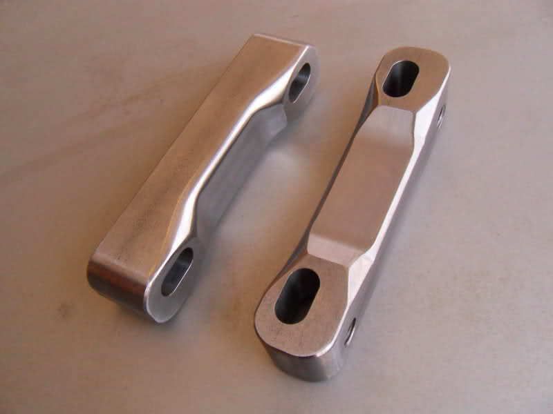
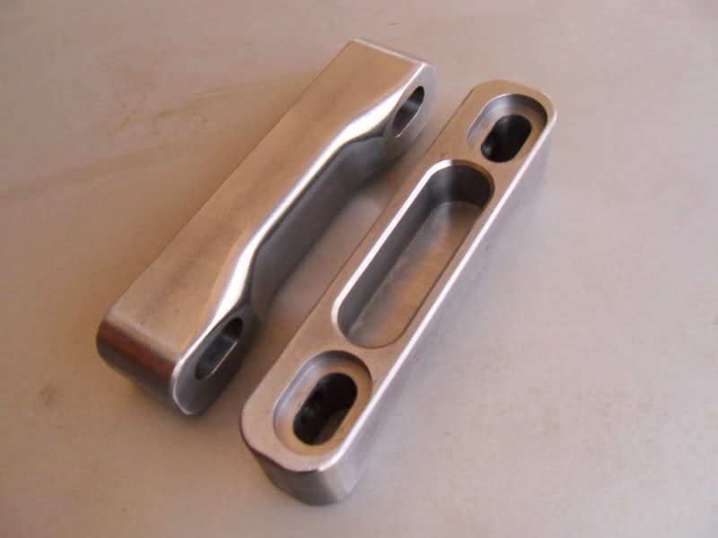
I will draw the piece today and send you a file. All you have to do is send it to someone with a plasma, laser or waterjet and they can cut it.
I have specs on Toyota balljoints and Mazda ones also. So it's not a big thing. I just have to find the files in my control arm stuff.
You going to run Toyota spindles on a Mazda?
S
slowroller
+1y
We have 10 lasers and 5 plasmas at my work, so I could get them cut cheap if your interested. I don't run them I'm a cnc mill programmer and operator.
S
slowroller
+1y


There are so many variables with a drag link setup this is what I would recommend.
Take the existing front clip you have and set up a bump steer gauge. Basically is a plate that bolts to the spindle and a dial indicator on each side. You cycle the suspension and watch the toe change on the indicators.
Then you can move the points around and jig them up or clamp them and see the effect it had on toe.

vsawmike
+1y
Ahhh yes I can certainly do that. I have the clip on my frame table right now. I would just need to move it to the end and clamp it back down then cycle the suspension.
I am thinking that running larger wheels (either 18" or 20") would make me need to put the tie rod in the bottom of the little arm on the spindle. Do you know the name of that arm?
Also what got rid of the bump steer in your setup? Moving the arm down? More negative caster?
BY the way I appreciate any help.
Post was last edited on Aug 19, 2014 01:51. Edited 1
time.

vsawmike
+1y
You should run an S-10 upper balljoint instead. It fits the Toyota spindle, has more travel than a Toyota balljoint, is cheaper (less than $10 for the regular ones), comes in more variations (depending on manufacturer) and they also have a smaller bolt pattern.
However if you already have the Toyota balljoints they will work. I will have to make a template of the Mazda factory arm before I draw this so it will be this evening.
By the way I have CAD drawings for every kind of trucks arms, as I used to make tube arms for every kind of truck.
R
robert_paulsen
+1y
hey mike no i havent picked up the parts yet but thats why i touched base with you first was to get better options, s10 balljoints work on a yota spindle was not aware of that. nice, lets go ahead and do the s10 balljoint mazda arms and yota spindles. im trying to get all my parts in a row so i can have the stuff needed to do the 5 lug swap and this is first. what would you recommend material wise it be cut out of 3/16" or 1/4". hell if you dont mind can you do one of each s10 and yota on mazda arms toyota spindles?
Related Discussions in Mazda Projects
Thread
Posts
Last Post
852

last post by
skrapinsask +1y
150

last post by
cherokeed +1y