1990 B2200 Ground Up
S
sierrax
+1y
Any updates?

vsawmike
+1y
I will update saturday. I am on the carnival triumph on vacation right now.
S
sierrax
+1y
Well in that case enjoy yourself! Have a good one.

vsawmike
+1y
Thanks

vsawmike
+1y
Well just before I went on vacation I worked on the fuel tank area. I added the 2" square tube that will be the main structure and then below that I added 1" square tube.
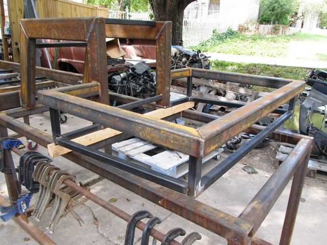
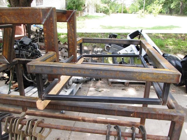
I made measurements for the fuel tank. I made CAD drawings for the guy that cuts my pieces. Just have to send them.
I also made drawings for the frame gussets, 4 link tabs, watts link tabs etc.
The weekend before I drove the sportage for the last time. I drove it into the driveway for it's final under its own power voyage. I pulled the engine, trans, drive shaft, fuel tank and all wiring front to back except door wiring.
I basically gutted the sportage. I took plenty of pics all the way thru so I can hopefully figure out where it all goes. I am sure I will have to strip all the harnesses of any un wanted wires.

vsawmike
+1y
The rear setup will be a 4 link with a watts link. The link bars will be somewhere between 18" and 24" depending on mounts. I think I can put the bags on the bars at about 3/4 of the way back from the front mounts.
There will also be two adjustable bars under the rear axle from the front bottom of the step notch to the back bottom. This should negate any flexing in the notch area.
I went to my brother's today and brought home my lathe. It's an old 12"x36" Craftsman lathe and it's worn smooth ass out. But it makes some nice bushings and other turned pieces. I will need it when I start making the 4 link, watts link and the control arms.
I also picked up the engine/trans with the hoist last weekend and lifted it over the frame on the frame table. I just wanted to see how well it might fit. I bought some new motor mounts for it. It looks like I will need to mod the oil pan, which I already new I was going to have to do.
I will also have to widen the front of the frame forward of the control arm mounts. I will need more room for the steering arm. The steering being so close also means I will have to move the Kia power steering pump from the right lower to the right upper or somewhere else. The only two pieces I just have to have on the engine are the alternator and power steering pump. I really need to run a York on there as well but it can be way up over the frame if I have to. There are plenty of pulleys on the Kia engine.
Post was last edited on Sep 29, 2014 02:36. Edited 1
time.

vsawmike
+1y
As far as locating the engine goes I am going to go by the location of the mounts on the factory frame. I drew some in CAD and should have them mid week. I know that front to back location will be close to the same as in the truck. I may be able to move it back an inch or maybe two. I will have to see how much clearance everyone else has there. Mine the firewall will be fabbed so I can do whatever there.
The height of the engine in the chassis is set by an absolute. That absolute is the auto trans oil pan. Since it cannot be modded in depth of 1/4" or more I feel like there is no sense in that. So the bottom of the trans oil pan sitting 1/2" above the bottom of the frame rails will be fine.
However this puts the engine oil pan about 3/4" below the bottom of the frame rails and also right where the engine crossmember is. So I will yank the oil pan and re work it and the sump to fit inside the frame rails and behind the engine crossmember. I will add a 3/16" thick plate on the bottom angled up at the front and back just in case it comes in contact with anything on the ground.
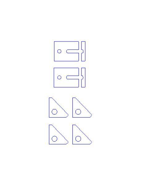
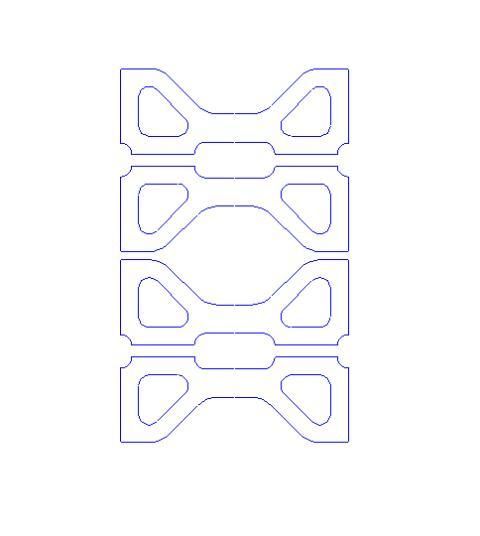
I ordered factory B series motor mounts as I stated above I drew the pieces for the frame in CAD. This is what the pieces look like before welding. They are drawin from measuring the factory mounts on the frame.
I also drew frame braces for the rear step notch. These will go into the top and front of the notch and the top and rear of the notch and will weld to each other.
And here are all the 4 link tabs.
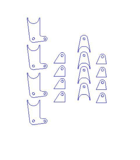
And here are the watts link cranks. I actually drew these while I was on the cruise. I took my laptop and it has solidworks on it. lol

I will have to import the files for the fuel tank. More to come.
The height of the engine in the chassis is set by an absolute. That absolute is the auto trans oil pan. Since it cannot be modded in depth of 1/4" or more I feel like there is no sense in that. So the bottom of the trans oil pan sitting 1/2" above the bottom of the frame rails will be fine.
However this puts the engine oil pan about 3/4" below the bottom of the frame rails and also right where the engine crossmember is. So I will yank the oil pan and re work it and the sump to fit inside the frame rails and behind the engine crossmember. I will add a 3/16" thick plate on the bottom angled up at the front and back just in case it comes in contact with anything on the ground.
I ordered factory B series motor mounts as I stated above I drew the pieces for the frame in CAD. This is what the pieces look like before welding. They are drawin from measuring the factory mounts on the frame.

I also drew frame braces for the rear step notch. These will go into the top and front of the notch and the top and rear of the notch and will weld to each other.

And here are all the 4 link tabs.

And here are the watts link cranks. I actually drew these while I was on the cruise. I took my laptop and it has solidworks on it. lol

I will have to import the files for the fuel tank. More to come.

mymmeryloss
+1y
Great progress! Cant wait to see it start coming together

vsawmike
+1y
Well I think the first thing I need to so this weekend is get the front frame section modified. Then I need to yank the oil pan and set the motor down in the frame and get the mounts made. I will also make the trans mount at this time.
I may have to draw some pieces to be cut for the trans mount but at least I will have it sorted out. Then I can move on to mounting the steering box and making the drag link bar.
The engine is covered in oil so it will need a gasket set. I decided to do all the gaskets and the freeze plugs and maybe have the head surfaced and a valve job done depending on how it looks.
My overall plan right now is to get the chassis rolling. So I will also need to yank the axles and send them to be shortened. That will determine what offset to order the rear wheels. The rear wheels will be 22" I think. More to come.
Anyone know what tire size looks good on a 22" wheel?

mymmeryloss
+1y
Did u come up with a steering solution? My rhd box is for sale.
Related Discussions in Mazda Projects
Thread
Posts
Last Post
852

last post by
skrapinsask +1y
150

last post by
cherokeed +1y